
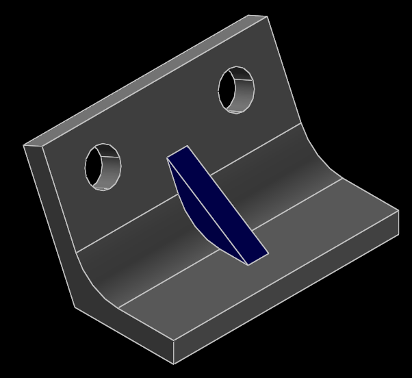
An introductory tutorial is available, in which we draw the same part that is shown in the demo video. This covers most of the basic features of SolveSpace, including sketches, constraints, extrusions, and Boolean operations.
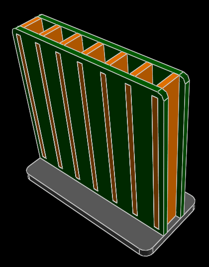
An assembly tutorial, in which we combine multiple parts into a parametric assembly. We use constraints to define the positions and orientations of the parts within the assembly. This means that we can modify the parts and regenerate the assembly, and the parts will remain assembled in the desired configuration.
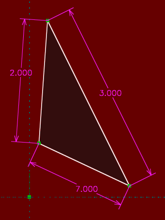
A tutorial on constraints. We look more closely at the geometric meaning of constraints in SolveSpace, and the ways that an incorrectly-constrained sketch will fail. We constrain a simple sketch in several different ways, and use the tools that SolveSpace provides to debug after overconstraining it. We also look at sketches with multiple solutions, and constraints both in 3d and projected into a workplane.
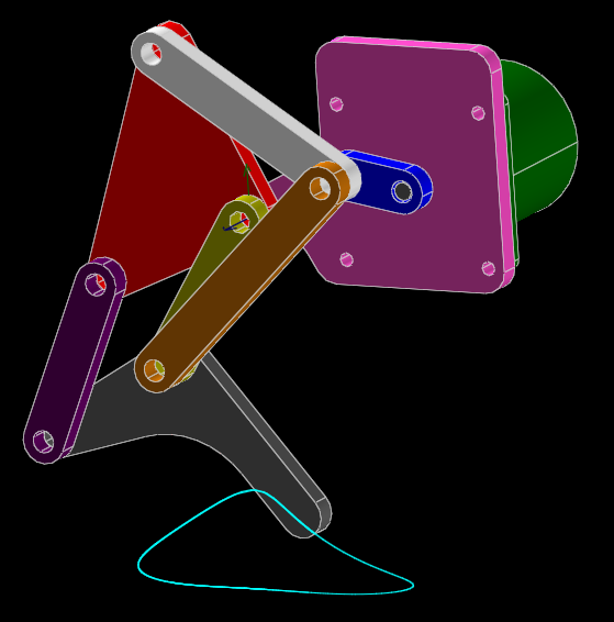
A tutorial on linkages. We use geometric constraints to model a planar linkage; we then displace one of the links, and let the constraint solver calculate the resulting geometry. We use this to plot the coupler curves of the linkage, and to animate a solid model attached to our linkage's skeleton. We also look at other kinds of linkages, with joints other than simple pin joints.
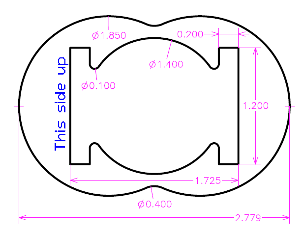
A 2d drawing tutorial. We use SolveSpace to draw a pure 2d part. So we start with a contour, and specify it using dimensions and constraints. We also use special tools to split lines and curves where they intersect, and trim them against each other, and to round sharp corners. After drawing the part, we place cosmetic dimensions on the geometry, and export a human-readable dimensioned drawing.
* * *
Thomas Knight has some additional tutorials (external site).* * *
And video tutorials are available for a range of topics. These tutorials were recorded using an earlier version of SolveSpace, so some slight differences in the user interface may be visible.