
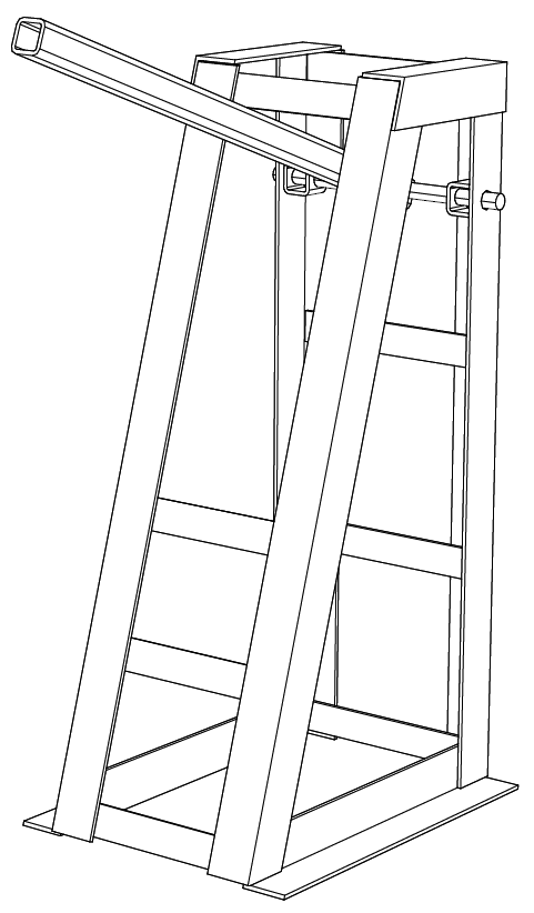
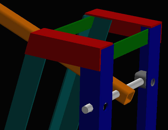
A stand made from notched angle iron. Notice the way that parts for the slanting front are constrained: point-on-plane constraints are used to fix the orientation (and not just the position) of one part to the correct angle. This means that a change in the angle of the other part will propagate through to the assembly without user intervention. Subsequent slanted parts are just constrained same-orientation against the first slanted part, in the same way that parts at right angles are typically constrained same-orientation against the coordinate (x, y, z) axes. So once the first slanted part is placed, we can specify the orientation of subsequent slanted parts with just a single constraint.
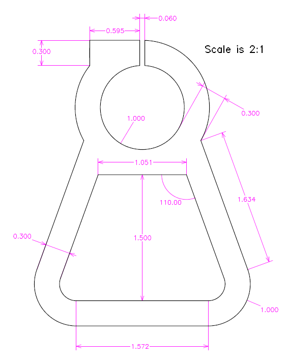
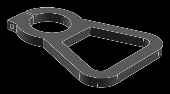
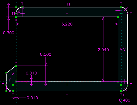
A mostly-2d part cut from sheet: a collet to clamp a 1.000" round shaft. The entire part is drawn in a single 2d sketch (except for the screw hole, which is out-of-plane). This is not necessarily the best way to draw the part; the part could instead have been drawn in multiple steps with Boolean operations, for example. But 2d parts may be drawn this way, and then not even extruded or otherwise modeled as solids. The sketch may be exported directly.
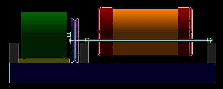
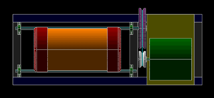
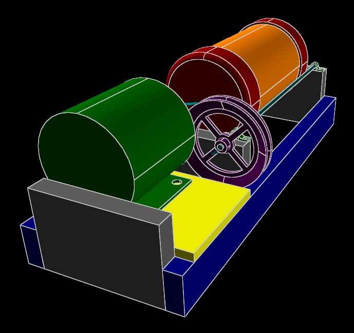
A belt-driven ball mill. The images above are a mixture of parallel projections, as for the top and side views, and perspective projections for the pictorials. All were generated directly from the 3d model.
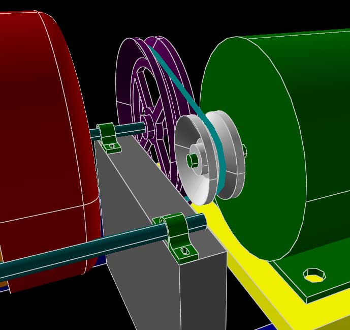
This model makes use of lathed (solid of revolution) features for the pulleys, and for the rounded end caps of the canister. It also uses a variety of assembly constraints, including point-on-line constraints (for example, to align the shafts to the bearings). Try lengthening the orange and red canister, and then lengthening the rest of the machine accordingly. This should require only changes to the dimensions, and the model will regenerate with the parts assembled as desired.
Note the group where the belt is drawn (g013-belt). The belt is drawn from lines and arcs constrained against the pulleys, and then "stretched out" using equal-length constraints and measured using a reference dimension.
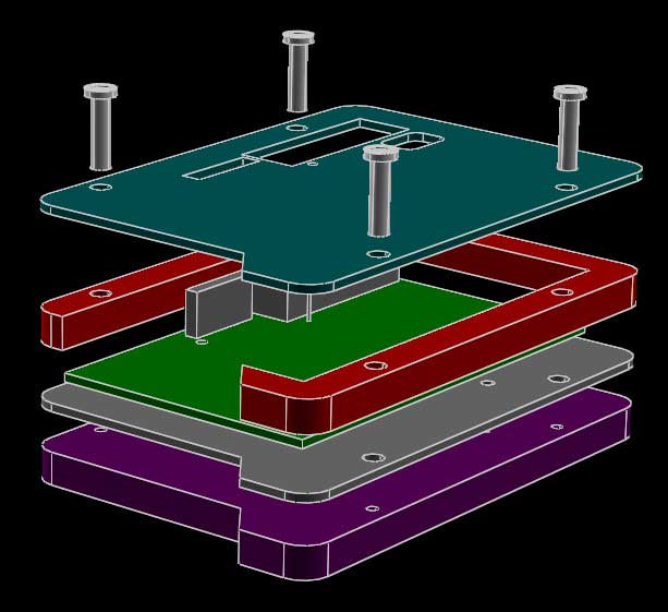
A case for a printed circuit board, made by stacking up four parts cut from sheet. The outline of the case is drawn only once, in outline.slvs. Each part that uses the outline (the top, the sides, a spacer sheet, and the base) imports that outline and modifies it as required. To change that outline, we can change it in a single location, and our changes will propagate through to all the parts.
Peaucellier's linkage. The rightmost point moves in an exact vertical line. This is only a demonstration of the constraint solver, and a mathematical curiosity. The linkage is too complex to be of practical value.
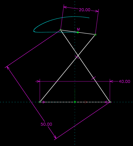
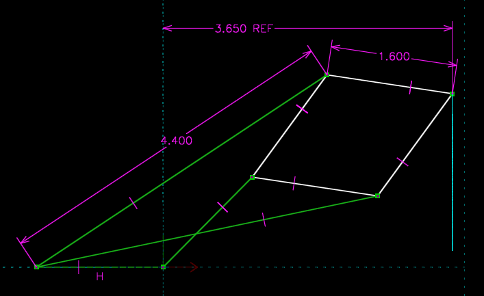
Chebyshev's linkage. The path traced by the midpoint of the short link approximates a straight line; and with only four bars, the linkage is practical.
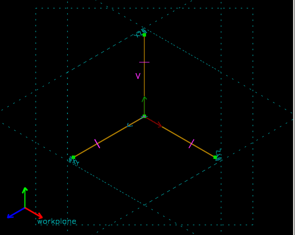
Geometric construction of an isometric view. We know that in an isometric view, the three coordinate axes are projected to the same length. So we draw our three coordinate axes, and then in a new group create a workplane, and constrain our coordinate axes to have equal projected length in that workplane. Since the coordinate axes cannot move, the workplane is rotated to produce the required projection; select the workplane's normal to read that projection out as a 3x3 rotation matrix.
(To get an isometric projection in normal drawing, you would just choose View → Nearest Iso View. This is a demonstration of the constraint solver, not a practical way to generate an isometric view.)