
In this tutorial, we will look more closely at constraints. In SolveSpace, we will almost always use constraints to specify the geometry of our sketch. It's also possible just to drag points with the mouse, or to place them on a regular snap grid; but a careful choice of constraints will make the design intent of the drawing obvious, and save us from recalculating the geometry of our part by hand every time a dimension changes.
A constraint is a geometric fact about the sketch. For example, a length constraint tells the solver that a given line segment should have a given length. The solver will try to move the points and other entities in the sketch in such a way as to satisfy all the constraints. But depending how the constraints are specified, it may be impossible for the solver to do so, or the result may not be the intended solution.
In this tutorial, we will constrain a simple sketch, and look at some of the ways that our constraints can fail. We start with a triangle, made from three line segments. The sketch already contains three constraints: the endpoint of each line segment is joined to the next using a point-coincident constraint, which was inserted automatically as we drew the line (by choosing Sketch → Line Segment, and clicking vertex A, B, C, and then A again). The point-coincident constraints are drawn as tiny magenta dots at the centers of the green square points.
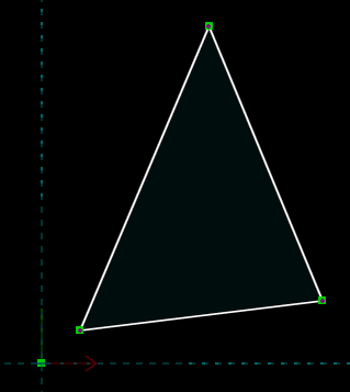
Initially, we can drag any of the three vertices of the triangle. Each point lies in the XY plane; so each point has two degrees of freedom, X and Y. This means that the overall sketch has six DOF.
We can restrict those degrees of freedom with constraints. Select one of the line segments by left-clicking it, and choose Constrain → Distance. This constrains the length of that edge, initially to whatever length it was drawn with. We can modify that length by double-clicking the dimension and typing a new value, and the solver will modify the sketch accordingly.

This constraint removes one DOF, so the sketch now has five DOF. To confirm this, go to the home screen in the Property Browser (by pressing Esc, or clicking the home link at the top left), and select the sketch, probably g002-sketch-in-plane, from the list. A list of constraints appears, and the number of degrees of freedom is indicated.
We can similarly constrain two internal angles of the triangle, by left-clicking to select the two adjacent edges and then choosing Constrain → Angle for each vertex. Each angle constraint removes one DOF, so the sketch now has three DOF.
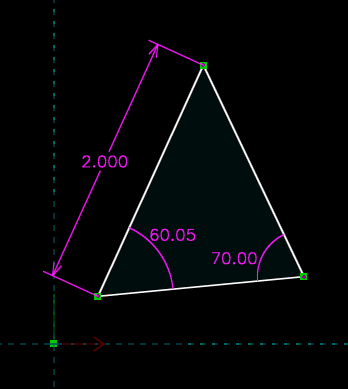
We can still drag any of the three vertices of the triangle, and it will move; but now the entire triangle moves with it, and the shape of the triangle does not change. This makes sense. From high school trigonometry, we know that we can fully describe a triangle by angle-side-angle. This means that the only degrees of freedom remaining are the translation (two DOF, X and Y) and rotation (one DOF, rotation theta about the Z axis) of the triangle, which moves as a rigid body in the plane. So the triangle should have three DOF, and it does.
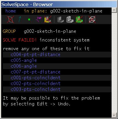
We could attempt to constrain the length of another side of the triangle, again by choosing Constrain → Distance. If we do so, then we see that the background of the sketch turns red, to indicate an error. In the Property Browser, we are informed that the solver has failed. This is because we have attempted to overconstrain the sketch. We had already specified enough constraints to exactly describe our triangle. This means that any additional constraints are not useful—either they are redundant, in which case they add no information, or they are inconsistent, in which case they can't ever be satisfied.
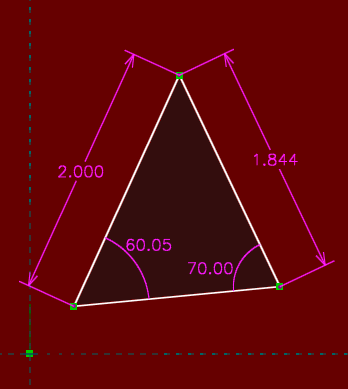
As a convenience, SolveSpace determines which constraints could be removed to fix the problem. Of course, it is possible to fix the problem by removing the constraint that we have just added, since the sketch was okay before. But it's also possible to fix the problem by removing one of the angle constraints, for example. This again makes sense, since we know that we can fully describe a triangle by side-side-angle.
Note that even though portions of the sketch are overconstrained, it still has unconstrained degrees of freedom. There are still no constraints that specify the translation of the triangle with respect to the origin, for example, or its rotation with respect to the coordinate axes. It would always be an error if we tried, for example, to constrain five DOF in a sketch with only four DOF to start with. But it's still possible to have an error with fewer constraints than degrees of freedom, if those constraints will overconstrain some DOF and leave others free.
If the sketch fails to solve, then it's important to fix the problem immediately. If more constraints are added while the sketch is inconsistent, then it will become very difficult to determine what's wrong. It's always possible to revert to the previous set of constraints by choosing Edit → Undo.
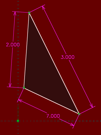
A related error occurs when the constraints are not inconsistent, but still cannot be satisfied. Below, we have attempted to draw a triangle with side lengths 2, 3, and 7. This is impossible, since 2 + 3 = 5 is less than 7—the triangle cannot be closed. A triangle could ordinarily be specified in terms of those three line lengths (side-side-side), but the particular values of the dimensions specified here are invalid. This causes a different type of error; technically, the result is that the solution does not converge.
The solver once again reports the error, and once again reports a list of problematic constraints. By removing one or more of the unsatisfied constraints, or just by choosing Edit → Undo, we restore the sketch to a legal configuration.
It was relatively straightforward to count degrees of freedom with our triangle: each point started with two DOF, and each length or angle constraint removed one DOF. But for some entities and constraints, the situation is more complex. A point-symmetry constraint, for example (Constrain → Symmetric) fully determines the location of one point in terms of the location of the other point. Since that point originally had two degrees of freedom, this means that the constraint must restrict two DOF, not just one. Most constraints restrict only one DOF, but some restrict two, and some constraints in 3d restrict three.
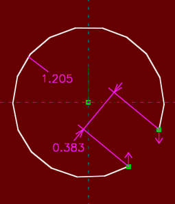
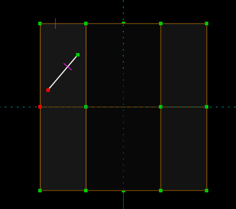
Sketch entities can be similarly complex. An arc, for example, is drawn with three points (the circle's center, and the arc's two endpoints), but it has five degrees of freedom (for example, its center X, center Y, start angle, finish angle, and radius), not six. Consider the arc shown below. We've specified its diameter, and we've constrained its center to lie at the origin (by selecting its center, selecting the origin, and choosing Constrain → On Point), and we've constrained the distance between its endpoints. We now wish to place the two endpoints of the arc symmetric about the horizontal axis.
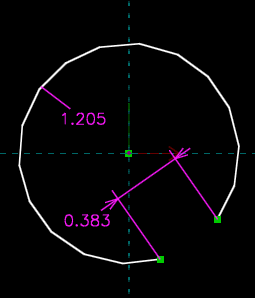
We might first think to choose Constrain → Symmetric. But if we do so, then we will find that the sketch fails to solve. This is correct behavior, since we have overconstrained the sketch. We can convince ourselves of this just by counting. The arc started with five degrees of freedom. We placed its center at the origin, which removed two, leaving us with three. The diameter constraint removes one more, and the distance constraint between its endpoints removes another. This leaves us with only one degree of freedom, and we determined above that the point-symmetry constraint removes two. It therefore must overconstrain the sketch.
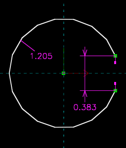
We should instead just constrain the two endpoints of the arc to be aligned vertically (by selecting them, and then choosing Constrain → Vertical). This removes only one degree of freedom; and since the points lie on the circle, by constraining them vertical they also end up equidistant from the horizontal axis and therefore symmetric.
As we've seen, it's very difficult to determine ahead of time exactly how many degrees of freedom a given portion of a sketch will have, and which constraints are appropriate. This means that as we draw and constrain the sketch, we will periodically encounter these types of errors. It's not a very big problem when we do; we can use the list of failing constraints (or, if not that, Edit → Undo) to refine our sketch, and choose constraints that are correct and reflect our design intent.
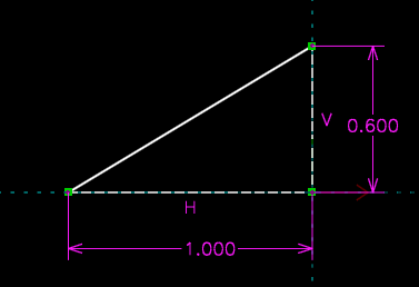
In some cases, the constraints that we specify will be ambiguous. Consider the triangle below:

One edge of this triangle is horizontal, and another is vertical; so we've specified one of its angles to be ninety degrees, and we've specified its rotation. We've dimensioned two side lengths, which means that the shape of the triangle is fully determined, side-angle-side. The ninety degree vertex lies at the origin, so we've specified its translation. This means that the triangle should be fully constrained, with zero degrees of freedom, and that's what SolveSpace reports.
But in fact, three other solutions exist that would satisfy these constraints. The horizontal edge could just as well go to the left as to the right, and the vertical edge go down as up.
When the sketch is ambiguous, with finitely many possible solutions, SolveSpace chooses among them according to the initial configuration of the sketch. Before we placed our constraints, we had drawn our triangle in the upper right quadrant. SolveSpace therefore chose the solution with the triangle in that quadrant. If we had initially drawn the sketch in a different quadrant, then SolveSpace would have chosen a different solution.
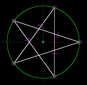
A sketch of any complexity will almost always have multiple solutions. Below, for example, we've drawn a five-sided figure, with equal side lengths and with all of its vertices lying on a circle. We intended to draw a regular pentagon.
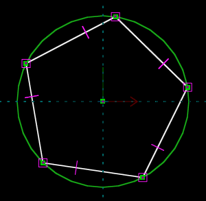
But the solver might also return a five-pointed star, or a triangle with one of the edges retraced twice, or five zero-length line segments at a single point on the circle. The choice will depend on the initial configuration of the sketch, so it's important to draw the sketch as close as possible to the desired geometry before constraining it.
While dragging a point on a sketch, the solver may sometimes switch from one solution to another. Sometimes this is desired, but other times it is not. If the sketch "flips", then try dragging slower. This means that the requested change will occur as several small changes, instead of one large change. The solver is therefore able to return everything to a valid configuration after each small change, and is more likely to get the same solution each time.
Similarly, if an undesired "flip" occurs when changing a dimension, then try making the change in multiple steps. For example, instead of changing it from 1 to 2, change it from 1 to 1.5, and then 1.5 to 2. This may be automated by choosing Analyze → Step Dimension.
Some constraints are more prone to multiple solutions than others. Point-to-point distance (and, equivalently, line length) constraints tend to generate multiple solutions; but point-line distance or point-face distance constraints do not, since they internally operate on "signed distance". This means that if a point is constrained to lie an inch above a line, then the solver will not accept a solution with that point one inch below the line. This reduces the number of possible solutions.
So far, we have been working entirely with constraints in the plane. We happened to be drawing in the XY plane, as we might, for example, if we were drawing a 2d part. But if we were drawing in some workplane in a complex 3d part, then everything would behave identically, provided that our constraints referenced only entities within that workplane.
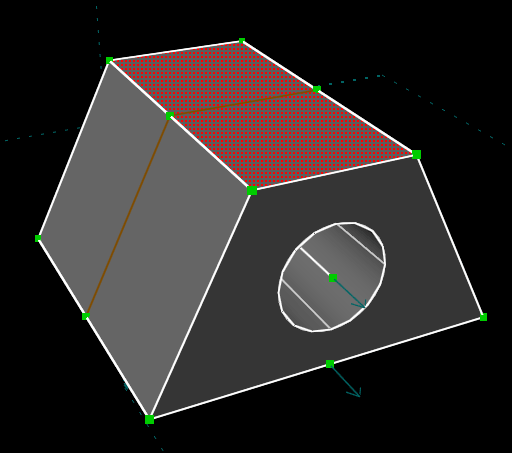
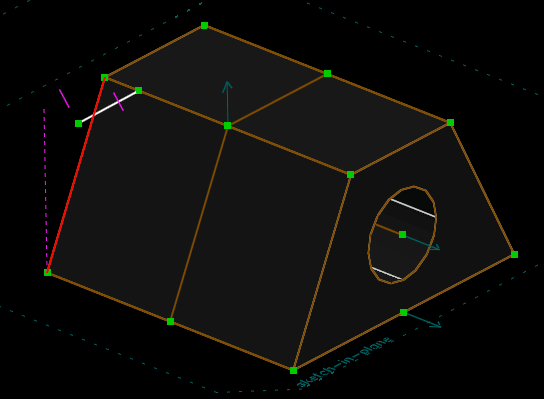
But constraints can also apply in 3d, or to entities outside of our workplane. Consider, for example, the part shown below. We've drawn a trapezoidal sketch (with a hole in it) and extruded that, and we are about to sketch onto the highlighted face of the resulting solid.
We've drawn a line segment in our new sketch, which appears in white. We wish to constrain it to have the same length as the line that's indicated in red below. We can do that by selecting our new line, selecting the red line, and choosing Constrain → Equal Length. If we do so, then the two lines now appear to have the same length.
But if we rotate the view and look in 3d, then we see that the original edge (which is highlighted in red below) is in fact much longer. It appeared shorter only because of our view, where we were looking at it almost on edge. The constraint operated on that projected length, and not the true length of the lines.
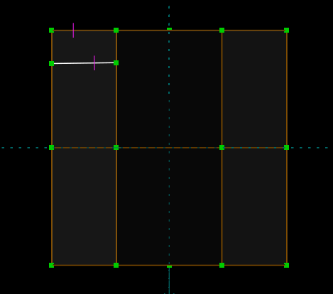
In many cases this is what's desired. For example, we may want to constrain the two points indicated below to lie on top of each other, in order to place our white line segment. Looking at the sketch in the our workplane, this seems like a reasonable thing to do.
But in fact, the lower point does not lie in our workplane. We're sketching on the top of the trapezoid, and that's a point from the bottom. This means that it would be impossible to make those two points truly coincident. But since the point-coincident constraint applies projected into our workplane, it will work as expected.
If we want to apply a constraint in 3d, and not projected into our workplane, then we can choose Sketch → Anywhere in 3d. This will cause constraints to apply in true 3d. So if we do that, and then delete our equal-length constraint and recreate it, then we will end up with a different result.
Our line is now much longer; its length is equal to the actual length of that other edge. Remember to switch back to the workplane (Sketch → In Workplane) after creating the constraints in 3d. Otherwise, we might create constraints or entities in 3d by accident. (By default, when we're sketching in a workplane, a line, circle, or other entity will be created in such a way that it always lies in that workplane. But when we're sketching in 3d, the created entity will be entirely free. This means that it will require more constraints to place it.)
Dimensions are generally used to drive the geometry. When we dimensioned a line's length, for example, we wanted to change the length of that line to whatever we indicated with the dimension. The dimension was an input to the sketch.
In some cases, we might want the reverse: we might want the geometry to drive the dimension, so that the dimension just indicates to us whatever some length or angle happens to be. The dimension would in this case be an output from the sketch. Such dimensions may be created, as reference dimensions. To do so, first create the dimension normally. Then select the dimension, and choose Constrain → Toggle Reference Dim.
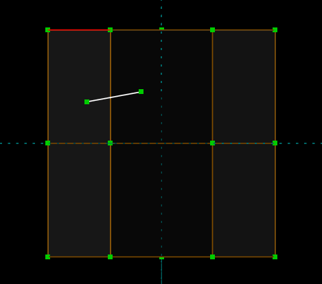
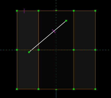
Consider the sketch below. We've drawn two lines. We've placed a regular dimension on the bottom line, and a reference dimension on the top one. We are about to drag the point that's indicated in red.
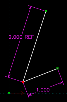
As we drag, the 1.000 inch dimension on the lower line will maintain that line's length at one inch. That dimension will therefore not change. But the reference dimension will change as we drag, to indicate whatever length we've dragged that line to. Reference versions are available of all dimensions, including length, angle, and length ratio.
To learn more about a particular constraint, see its entry in the reference manual, or just place it in a simple sketch and experiment.
This tutorial has mostly discussed constraints for drawing, but the same constraints are also used for assembly. See the assembly tutorial for examples.