
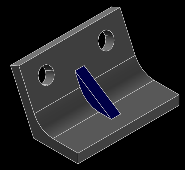
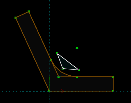
In this tutorial, we will draw the part shown below. This is an angle bracket, with a radiused inside corner and a gusset. Both legs of the angle, and the gusset, are the same thickness. There are two equal-diameter mounting holes placed symmetrically on one of the legs.
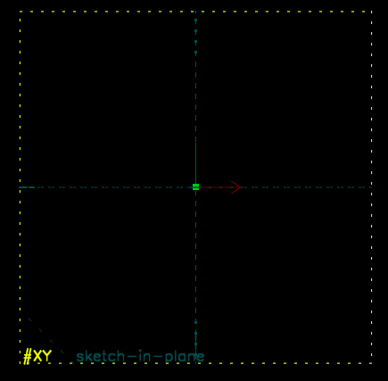
When we first run SolveSpace, we will begin with an empty part. Initially, our view of the part will be oriented onto the XY plane; the label for that plane is displayed at the bottom left of the screen (#XY, in dark grey). The axes are also indicated by the three colored arrows at the bottom left; the X, Y, and Z axes are drawn in red, green, and blue respectively.
When we hover the mouse over any entity, constraint, or other object in the sketch, that object will appear highlighted in yellow. For example, the XY plane, which is drawn as a dashed square, will appear highlighted when we hover the mouse over it. The YZ and ZX planes initially look like dashed lines, because they are being viewed on edge; but they still appear highlighted in yellow when we hold the mouse over them. It is similarly possible to highlight the X, Y, and Z axes (which are drawn as arrows), or the origin (which like all points is drawn as a green square).
To rotate our view of the part, click and drag with the center button (or the wheel) of the mouse. To pan, click and drag with the right mouse button. To zoom, use the mouse wheel, or choose View → Zoom In or Out.
Initially, we are sketching in the XY plane. After rotating the view by center-dragging, we could try to drag the view back to the XY plane, but it would be almost impossible to get it exactly correct. To return the view to the XY plane (so that our view is parallel to the XY plane, and centered at the origin), choose View → Align View to Workplane, or press W, or choose the equivalent button from the toolbar. (The toolbar button for "Align View to Workplane" is at the bottom right. To learn what a button on the toolbar does, hover the mouse over it; a tool tip will be displayed.)
We will construct this part by drawing the 2d cross-section of the angle, and extruding it to form the angle. We will then add the gusset using a Boolean union, and cut the mounting holes using a Boolean difference.
So to start, we must sketch the profile of the angle. This is made from line segments, plus one arc (for the radiused inside corner). We will start with the line segments; so choose Sketch → Line Segment, or the equivalent button from the toolbar. Then move the mouse pointer somewhere close to the vertical axis, but not exactly on top of it, so that nothing is highlighted. (By starting a line when something is highlighted, we can insert certain types of constraints automatically. But we don't want to do that now.)
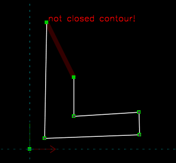
To start the line, left-click. To end the line, left click again. A new line segment will automatically be created, that shares an endpoint with the old line segment. As we draw, SolveSpace will warn us that the profile is not yet a closed contour.
Before left-clicking the last time, place the mouse over the first point of the first line that we drew. That point will appear highlighted in yellow. When we click, the endpoint of the line segment we were drawing will snap to that point, forming a closed contour, and we will stop drawing. (It would also be possible to stop drawing by pressing Escape, or by right-clicking. But here, we wanted to draw until we had a complete closed contour.)
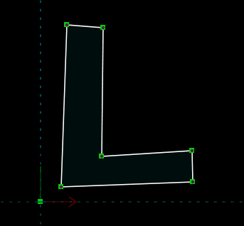
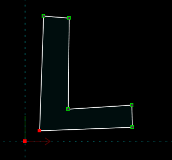
The profile now consists of six line segments, that join at six endpoints. We can move any of these endpoints by left-dragging with the mouse, and the contour will remain closed. The "not closed contour" message has disappeared, and the area inside the contour is shaded in very dark blue.
We can now use constraints to specify more about the geometry of this section. For example, we should place the bottom left corner of the profile at the origin. (Of course, we don't have to. But it will just make life easier for us later if we align our part to the coordinate system.) To do this, we hover the mouse over that bottom left point, so that it appears highlighted in yellow. We then left-click; the point now appears highlighted in red. This means that the point is selected. (To de-select the point, we could click it again, or press Escape, or select Edit → Unselect All. But we don't want to do that now.)
Similarly, we can select the origin by left-clicking it. In the Property Browser, we see that two points are selected. As a convenience, it tells us their exact coordinates (x, y, z), although we don't care about that now.
We want to put the bottom-left corner of the profile at the origin; so that means that we want those two points to be coincident. We can achieve this with a constraint. Choose Constrain → On Point / Curve / Plane to constrain point-on-point, or use the equivalent button on the toolbar. The origin can't move, so that bottom-left corner moves in order to satisfy the constraint.
We should also make the roughly-horizontal leg of the angle exactly horizontal. We can do this with a horizontal constraint on those line segments. So hover the mouse over the bottom line segment, and left click so that the line is selected. The line will be drawn in red, and information about the line will be displayed in the Property Browser; selection works the same for lines and curves as for points.
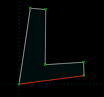
Now choose Constrain → Horizontal, or use the equivalent button from the toolbar. The line is now horizontal, and a small magenta H is drawn to indicate the constraint. The H appears in yellow if we hover the mouse over it; that constraint can be selected (and then deleted, for example) in the same way as for entities.
Repeat this process for the line just above that one, which should also be horizontal, and for the short rightmost line, which should be vertical.
The other leg of the angle is slightly more complicated. If this were a ninety degree angle, then those lines would be horizontal and vertical too; but it's not, so they're not. We do know that the two long lines should be parallel to each other. To constrain that, we first select those two lines by left-clicking them. They will both appear highlighted in red.

We then choose Constrain → Parallel / Tangent, or use the equivalent button in the toolbar. This forces the two lines parallel, and the constraint is indicated by the pairs of short magenta lines drawn parallel to and near the midpoint of each of the two line segments. Of course, all of the previous constraints still hold. If we drag one of the points, then the other points will move in such a way as to still satisfy all of the constraints.
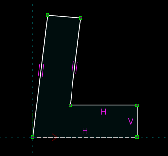
Then constrain the short endcap of the roughly-vertical leg of the angle to be perpendicular to either of the two parallel lines; it doesn't matter which one. (Just select the short line, and one of the parallel lines, and choose Constrain → Perpendicular. The constraint is drawn as a magenta perpendicular symbol near the midpoint of each of the line segments.)
And constrain the two short endcaps to have equal length, so that the two legs of the angle will have equal thickness. (Select the two short line segments, and Choose Constrain → Equal Length / Radius / Angle. The constraint is drawn as a single short magenta line, perpendicular to each line segment. SolveSpace inferred what type of constraint (equal length, equal radius, equal angle, etc.) was desired based on what was selected when we chose that menu option.)
Finally, we want to radius the inside corner of the profile. We could sketch an arc of a circle explicitly, and constrain it to lie tangent to the line segments where it joins. That would work, but SolveSpace provides a quicker way to get the exact same result. Select the inside corner point of the profile, so that it is highlighted in red. Then choose Sketch → Tangent Arc at Point; a tangent arc will automatically be created at that point. Drag the endpoints or center of the arc to change the radius.
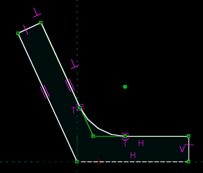
This completes our section. It's not fully constrained, so if we drag some of the points, then they still can move. This means that we can still adjust the geometry by dragging points with the mouse, but as we drag, all of the constraints that we have specified will be respected. It would be possible for us to add constraints until they completely described the geometry, so that it was impossible to drag anything with the mouse. But it's not necessary to do that, and we won't do that now.
Note that if we drag a point beyond certain limits (that depend on the constraints that we have specified), the sketch may fail to solve, or it may solve to an unexpected solution. In that case, it is always possible to go back by choosing Edit → Undo.
We can take our two-dimensional section, and extrude it to produce a three-dimensional solid. To do that, choose New Group → Extrude, or choose the equivalent button from the toolbar. This will create our extrusion. To see our extrusion, rotate the view by center-dragging with the mouse.
By default, extrusions are one-sided; so our original sketch is the beginning of our extrusion, and the solid is either entirely to the right or entirely to the left of that original sketch. We can change the extrusion depth by dragging a point on the extruded face.
But in fact, we would rather extrude on both sides, so that our original sketch forms the middle of the extrusion instead of its start or finish. That way our part will be symmetric about the XY plane. It's a good idea to draw parts with symmetry about the coordinate axes whenever possible, because it's usually simpler to construct the desired constraints when that symmetry exists.
In the Property Browser, SolveSpace has automatically shown information about the extrusion that we've just created. (If it didn't then we could view that information by choosing the "home" link at the top left of the Property Browser. We would then see a list of groups, including g003-extrude, the extrusion that we've just created. We could click on that name to view the same screen that is shown automatically. If the Property Browser is not visible, then choose View → Show Property Browser or press Tab.)
We can see that the extrusion, named g003-extrude, is one-sided. To change it to be two-sided, click "two-sided" in the Property Browser.
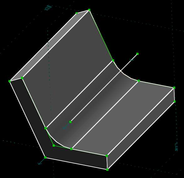
The extrusion now appears symmetrically about the XY plane, as desired. If we drag a point on one of the end faces of the extrusion, then the other end face will move to maintain the symmetry.
We now wish to sketch the gusset. We will need to create a new sketch, in a new workplane. We can place the origin of that workplane at the midpoint of the inside corner of that angle. That point exists, but it is currently not visible, because it lies within the solid object that we have just extruded. To make it visible, we must show "hidden lines", by clicking that icon at the top far right of the Property Browser. This causes all lines and points to be displayed, even if they lie within the solid model. (So it's as if the part becomes transparent.)
We have left-clicked to select that point here, so it is highlighted in red. We then center-drag the view so that we are looking at the extrusion roughly on end, and choose New Group → Sketch in New Workplane. This creates a new workplane, with origin at the selected point, and parallel to the XY plane. (If no other information is provided, then SolveSpace snaps to the nearest workplane parallel to the coordinate axes; so it was important for us to rotate the view so that it was approximately correct before we created the workplane. Otherwise, SolveSpace might have snapped to the YZ plane or the (Y, -X) plane or some other plane instead.)
When we create the new workplane, the view will be aligned to the workplane; so we will see the part rotate so that we are viewing the extrusion exactly on end. We could rotate the view out of that workplane by center-dragging as before, and then return the view to that workplane by choosing View → Align View to Workplane.
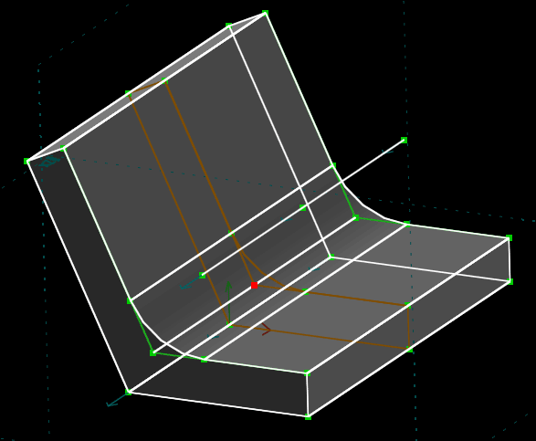
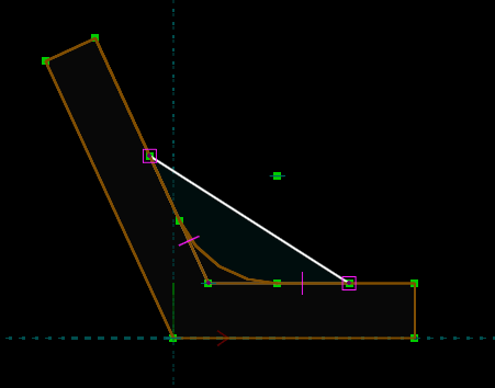
In that new workplane, we can draw our gusset. Choose Sketch → Line Segment. Left-click to begin the line, again being careful that nothing is highlighted when we click (to stop SolveSpace from inserting an automatic constraint that we don't want). As before, hover the mouse over the first point that we drew before clicking the last time, so that the contour is automatically constrained closed. The "not closed contour" warning will disappear, and the contour will be filled in very dark blue, as before.
One point of the triangle should lie exactly on the inside corner of the angle. (This is also the origin of our current workplane, although that doesn't matter now.) So select a point of the triangle, and select the inside corner of the existing extrusion, and choose Constrain → On Point.
The other two points of the triangle should each lie on one of the legs of the angle. So select one of the points, and select one of those line segments, and choose Constrain → On Curve. This creates a point-on-line constraint, which is drawn as a small magenta box around the constrained point. Drag the point; it will move along the line, but the constraint will be maintained. Repeat the process for the other point.
Finally, constrain the two legs of the gusset to have the same length. To do so, select both line segments, and then choose Constrain → Equal. This is the same equal-line-length constraint that we used in the first sketch.
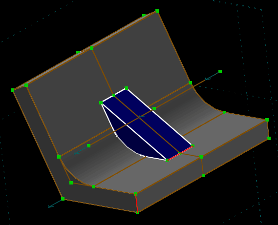
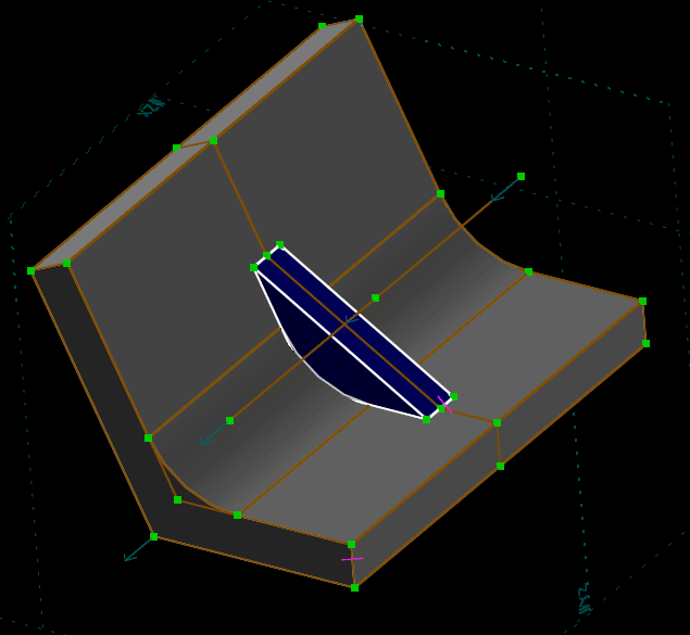
Once the sketch is complete, we can rotate our view (center-drag) to verify that we've drawn it in the right place. We can see that the sketch is at the center of the part—in fact, it lies in the original XY plane—and that two of the edges of our gusset lie coincident with the faces of the angle. This is probably a good time to re-hide the occluded lines, to make the view less confusing. Click the button in the far top right of the Property Browser twice more, to cycle from "occluded lines are dashed" through "occluded lines are solid" to arrive back at "occluded lines are hidden".
We then extrude that section, by choosing New Group → Extrude, in the same way as before. Once again we want a two-sided extrusion, so change that in the Property Browser. We can also change the color of the extrusion, by clicking on one of the color swatches. Notice that it was very simple to place the gusset in the middle of the angle bracket, because we originally drew the angle symmetric about the XY plane. If we hadn't, then we could still have drawn the gusset at its middle (for example, by placing a datum point and using a midpoint constraint), but it would have been more complex.
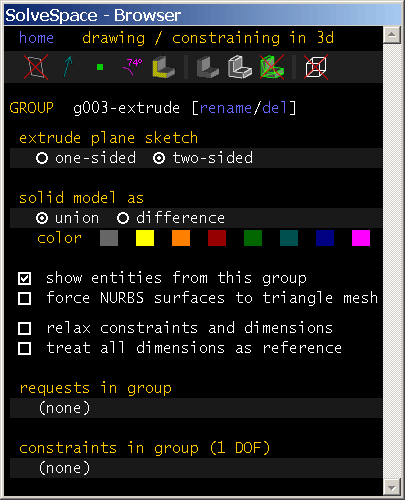
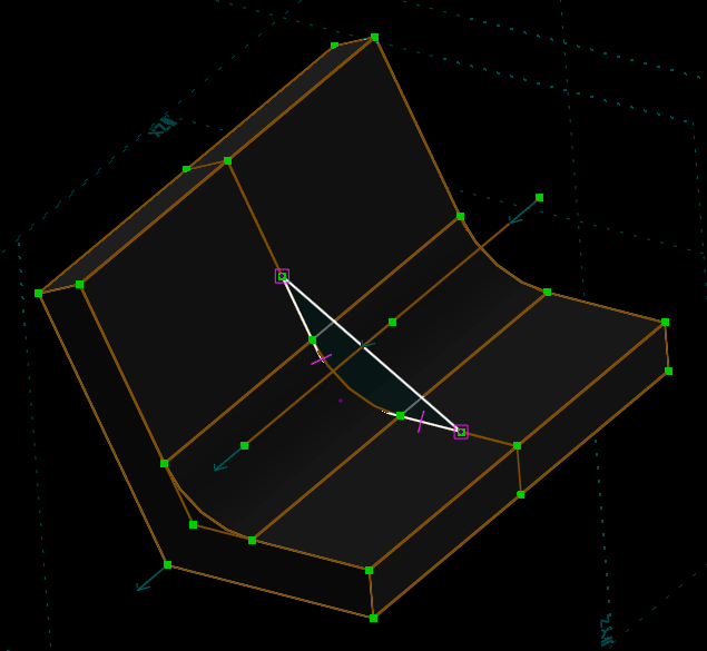
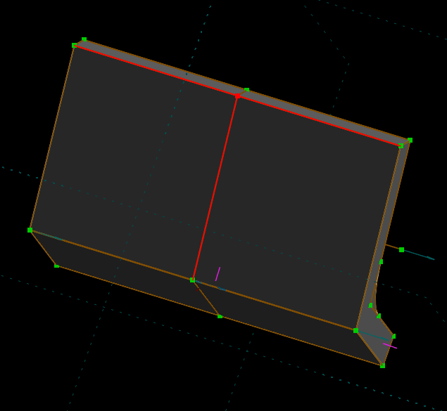
We can change the thickness of the gusset by dragging a point on either surface of the gusset. But we want the gusset to have the same thickness as the angle itself, so it's better to use a constraint. That way, the thicknesses will automatically get forced to be equal. We can do that by constraining a line along the thickness of the gusset to have equal length to a line along the thickness of the angle. Select those lines as usual, by hovering the mouse over them and then left-clicking. The selected lines will be displayed in red.
One possible choice of two lines is shown above; of course many others exist. After selecting, choose Constrain → Equal Length. This is the same constraint that we used earlier when we were sketching our sections to extrude. (There's actually a small difference; within the workplane, the constraint worked on 2d length, projected into the workplane; but now, it's working on real 3d length. We can choose which version we want, by choosing Sketch → In Workplane or → Anywhere in 3d. By default, SolveSpace assumes that we want to sketch and constrain within a workplane when we're working with a sketch-in-workplane group, and in 3d when we're working with an extrusion. That's what we want here, so we don't need to do anything special.)
The constraint has now forced the gusset to have the same thickness as the angle. Try dragging the various points on the model. For example, dragging a point on the original profile of the angle (at the midpoint of the extruded angle) will change the thickness of the angle. It will also change the thickness of the gusset, since the constraint determines the thickness of the gusset in terms of the thickness of the angle. If something unexpected happens while dragging, then choose Edit → Undo.
The part is now complete, except for the two mounting holes. We can draw those as another extrusion; except this extrusion, instead of adding material, should remove material to cut the holes. We must again create a new workplane, in which we will draw our section to extrude. (Most parts will have this structure of alternating sketches and extrusions.)
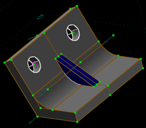
Before, we created our new workplane in terms of a single point, and then we let SolveSpace infer the orientation of the plane from the orientation of our view. That worked because our desired orientation was parallel to one of the coordinate planes. In this case, our desired plane is not parallel to a coordinate plane, because the angle bracket is not (necessarily) ninety degrees. So in addition to the point for the origin, we specify two line segments; the workplane will be defined so that both of the line segments are parallel to that plane. So select a point and two (non-parallel) lines on the back of the extrusion, for example the point and two lines shown below. Then choose New Group → Sketch in New Workplane.
The view is aligned to our new workplane, as usual. This time we want circles, so choose Sketch → Circle. Left-click to define the center of the circle, and then left-click again to define its radius. (To change the radius later, just left-drag the perimeter of the circle. And the center is a point that may be dragged like any other.) Repeat the process to draw a second circle.
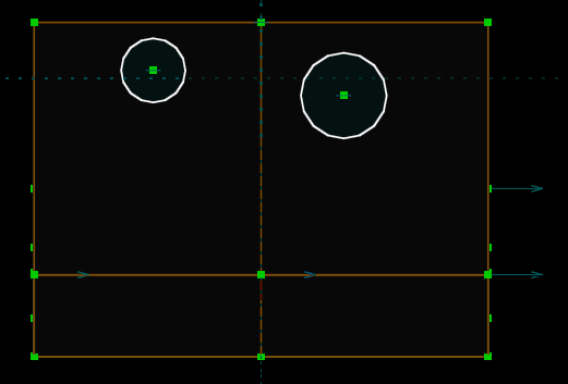
We want the circles to have the same radius/diameter, and to be placed symmetrically about the center of the part. Select each circle by hovering the mouse over it (so that it shows up highlighted in yellow) and then left-clicking. Then choose Constrain → Equal Radius. (Notice that the same menu item can be used to create many different kinds of constraint, depending on what is selected when we choose that menu item.)
To place the circles symmetrically, select each circle's center. Then choose Constrain → Symmetric. The symmetry constraint is drawn as a pair of magenta arrows, pointing inwards.
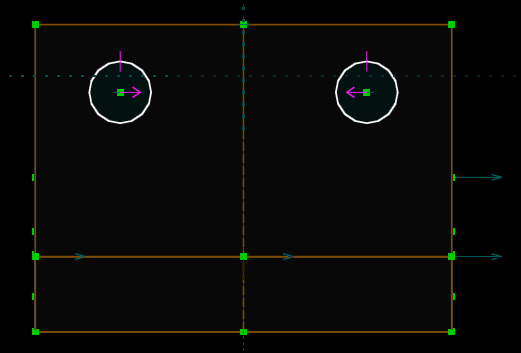
In this case, the points have been placed symmetrically about the vertical axis of the workplane (through the workplane's origin). Since no axis was specified with the constraint, SolveSpace inferred that we wanted either the horizontal or the vertical axis of the current workplane. Since the two circles' centers were initially drawn more horizontally than vertically, it inferred that we wanted the vertical axis. We could also have specified the axis explicitly, as a line segment or a plane, but it was not necessary for us to do so.
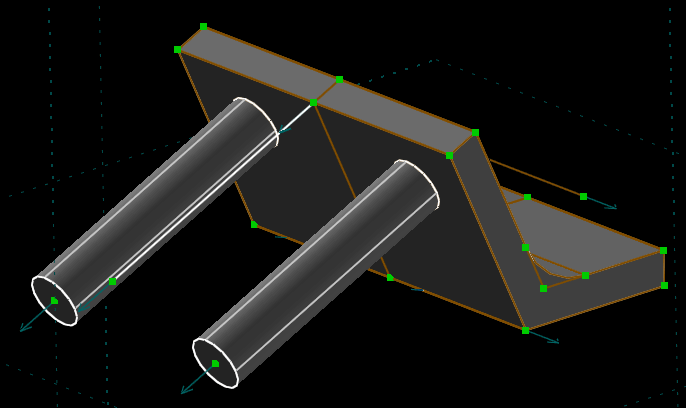
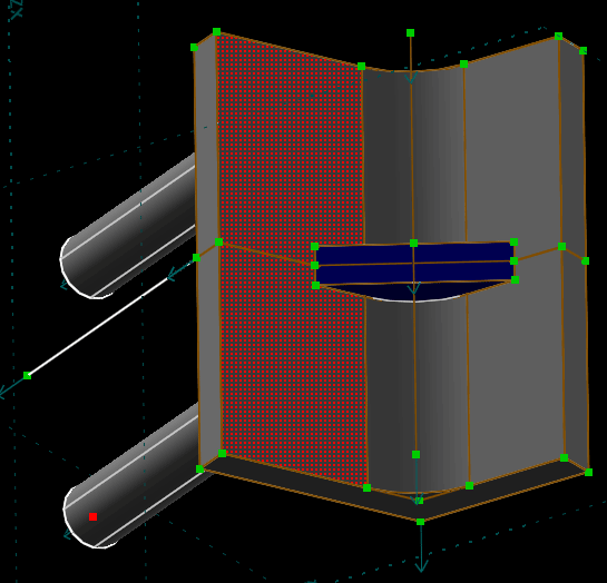
The section is complete, so as usual choose New Group → Extrude. This creates two cylinders, as shown below.
First, the extrusion is going in the wrong direction. We could fix that by dragging the end face of the extrusion to the other side. But once again, it's better to specify what we want exactly, using a constraint. Select the center of the circle on the extruded face. Then select the inside face of that leg of the angle, as shown below. Faces can be selected, in the same way that points or lines can be selected. Hover the mouse over the face, and it will appear highlighted in yellow. Left-click, and it will appear highlighted in red.
In order to select both the face and that point, it may be necessary to rotate our view of the part. This is not a problem.
Then choose Constrain → On Plane. This places the point on the plane, which sets the extrude depth and direction as desired.
In the Property Browser, modify the extrusion so that it is merged as "difference" instead of "union". This means that instead of adding material, this extrusion removes material. So the extrusion cuts two holes, and we're done.
Try dragging each point on the model, to see which degrees of freedom it manipulates. Some points cannot be dragged, because the constraints that we have specified completely determine their position. But we have not fully constrained the sketch, so most of the points can be dragged to change some parameter of the part.
Also, try going back and making some change to earlier sketches in the part. In the Property Browser, choose "home" (from the link at the top left of the Property Browser), or press Escape until we see a list like the one below.
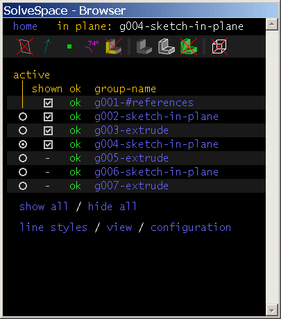
Each entry in the list corresponds to a group in the part. The first group is the references; that includes things like the XY plane and the origin. The references are created automatically, and cannot be modified. The first real group is g002-sketch-in-plane; when we started drawing, we were drawing in g002. This is a sketch-in-workplane group, where that workplane is parallel to the XY plane and centered at the origin.
We had then extruded g002 to form g003, an extrusion. We drew the gusset section in g004, and extruded it in g005. We drew the mounting hole section in g006, and extruded it in g007. SolveSpace maintains a history of the features with which we created our part, and allows us to modify them. If we modify something in an earlier group, then that change will automatically propagate into later groups, according to the constraints and other rules that we have specified.
For example, click the radio button in the "active" column for g004. We now see the section that we had drawn for the gusset. Choose View → Align View to Workplane to orient the view back on to that workplane, and make some change that sketch (by dragging the points, or dimensioning the length of one of the lines, or even adding some new geometry). Then click the radio button in the "active" column for g007, to see the finished part. Whatever changes we made to g004 have propagated through.
The current view of the part is rather cluttered. SolveSpace will generate many extra lines and points, because they might be useful to constrain against. To hide those, choose "hide all" on the Property Browser home screen. We now see only the lines and curves that actually form the edges of the solid model.
This solid model can be used in several different ways. We could just look at it, or export a screenshot using File → Export Bitmap. Or we could export a hidden-line-removed vector drawing, using File → Export 2d View. We could export a section of the solid by selecting a face of the model (to define the section plane), and then choosing File → Export 2d Section.
We also could export the three-dimensional solid model itself, either as a triangle mesh or as a STEP file. Most CAM or rapid prototyping software expects some type of solid model as input. It's generally better to use STEP files when possible, since they represent curves and curved surfaces exactly (vs. triangle meshes, which are only an approximation).
This tutorial has covered only the basics of SolveSpace. Many other features exist, including a wide range of entities and constraints, 2d and 3d parametric assembly, and various analysis and export functionality. See the reference manual for more information, or the other tutorials.
The part drawn in this tutorial is available for download: